Three Cups, One Wobble, and a Northwest Gust
10:42 — Wind’s been gusting all morning. Can hear it against the window. Perfect day to start building a device that measures exactly what I’m already annoyed by.
10:51 — The Beaufort scale is older than I thought. Francis Beaufort invented it in 1805, but here’s the thing: it had nothing to do with numbers. The original scale described what a frigate’s sails could handle. “Just sufficient to give steerage” at one end. “That which no canvas sails could withstand” at the other. Wind speeds in km/h weren’t attached until 1923.
10:58 — This changes my approach. I don’t need the dial to show 23 km/h. I need it to show “leaves rustle” versus “small twigs in constant motion.” Pilot’s intuition, not a digital readout.
11:07 — Browsing old anemometer patents. Thomas Romney Robinson invented the cup type in 1846. Four cups on a rotating cross. He claimed the cups always moved at one-third the wind speed regardless of cup size or arm length. Every other scientist believed him for decades. Then someone actually checked. Wrong. The ratio depends on the exact dimensions and can vary from 2 to 3.5.
11:14 — What this means for me: I cannot copy someone else’s calibration. The anemometer factor depends on my cup geometry.
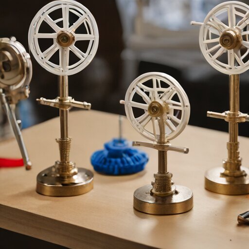
11:29 — First CAD sketch. Three cups, not four. John Patterson worked this out in 1926 — three cups respond faster to gusts and produce more consistent torque. Each cup hits maximum torque at 45 degrees to the wind. Patterson was Canadian, which I only mention because I am also Canadian and we’re allowed to be smug about meteorological equipment sometimes.
11:45 — Cup shape: hemispherical. The drag coefficient is 0.38 on the outside, 1.42 on the inside. Nearly 4:1 asymmetry. That’s the entire mechanism — wind pushes the hollow side harder than the round side, and the difference creates torque.
12:03 — Problem one: how do I translate rotation into a dial reading? The orrery escapement used discrete ticks, but wind speed is continuous. I need a different gearing approach. Maybe a centrifugal governor that rises with speed and pushes against a dial arm?
12:18 — Actually, no. Too complex for day one. Simpler: the cup wheel drives a worm gear into a dial. One revolution of cups equals one increment on the dial. The faster the wind, the faster the dial climbs. A return spring pulls it back toward zero when the wind drops.
12:34 — Modelling the hub assembly. Need a brass bushing — learned that lesson on the orrery. Printed-on-printed bearings have too much friction and wobble.
12:51 — Lunch break. Still windy.
13:22 — Back at it. Vane design for direction. The term for a direction-only indicator is “anemoscope.” A speed-only indicator is “anemometer.” I’m building both, so… vane anemometer? Anemoscopic anemometer? The vocabulary gets tangled.
13:38 — The vane needs the pivot point forward of the geometric centre. Otherwise it won’t weathercock properly — it’ll just oscillate or hang crooked. Common beginner mistake apparently. Making the tail surface larger than the pointer surface.
13:55 — First print started: the cup wheel assembly. Module 1.0 teeth this time, finer than the orrery gears. Feeling optimistic.
14:37 — Print done. Cups look acceptable. The arm connections to the central hub are a bit stringy.
14:44 — Test fit with the brass bushing. Wobble. Of course there’s wobble. I’m 0.1mm off on the bore diameter.
14:52 — Adjustment. Reprinting hub only.
15:19 — Better. Spins freely on the bushing with minimal lateral play.
15:28 — Taking it outside. Cold. Wind hitting my face from the northwest.
15:31 — The cups spin. Unevenly, but they spin. The wind is gusty enough that the wheel accelerates and decelerates in bursts. I can see Beaufort 3, maybe 4, in the motion. “Leaves and small twigs in constant motion” — that’s about right for what I’m feeling on my face.
15:35 — Brought it back in. Noted that I have no idea how to actually count revolutions per unit time without a sensor. Need to think about the mechanical readout linkage more carefully.
15:47 — Sketching a dial face. Eight compass points around the edge for direction. Concentric arcs in the centre for speed, labelled with Beaufort conditions instead of numbers. “Smoke rises vertically.” “Wind felt on face.” “Small branches move.” “Whole trees in motion.” That last one is Beaufort 7, around 50-60 km/h. Higher than I’ll ever test on a desk-sized model.
16:02 — The vane needs to drive the direction dial through a gear or friction coupling. That’s a second rotational axis at 90 degrees to the cup wheel. Both outputs need to converge on a single display face.
16:14 — This is getting complicated. The orrery was one problem: encode time into gear ratios. This is two simultaneous problems: direction and speed, both updating continuously, both feeding one instrument.
16:23 — The Tower of the Winds in Athens did this 2,000 years ago. Bronze Triton statue held a rod for direction while sundials and a water clock handled time. Eight wind gods carved into the octagonal walls. Integrated multi-axis meteorological display, circa 50 BC.
16:31 — Reassuring that the problem is old. Not reassuring that my solution involves printer filament instead of Pentelic marble.
16:40 — Session ending. Have a spinning cup wheel and half a plan. No working dial. No vane. No housing. The wind is still audible outside.